High-efficiency Design, Supply, Installation, and Energy Audits by C
MATIC CONTROL LLP.
Pneumatic Systems & Automation
Compressed air is a vital utility in modern manufacturing, but
traditional distribution networks built from Galvanized Iron (GI)
or Mild Steel (MS) suffer from internal corrosion, scaling, leaks,
and severe pressure drops.
Aluminium Compressed Air Piping Systems have
emerged as the modern gold standard, guaranteeing clean air
delivery, zero rust, and optimal energy efficiency.
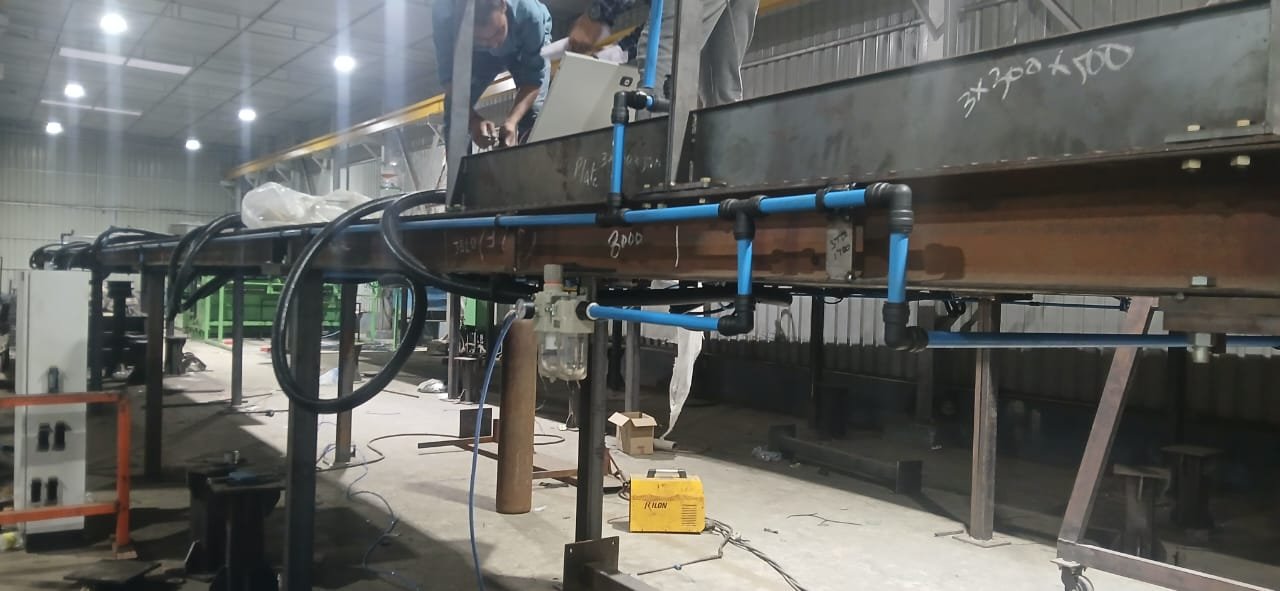
As an engineering partner and turnkey specialist,
C MATIC CONTROL LLP provides end-to-end Design,
Supply, Onsite Installation, and Audit services for
Aluminium Compressed Air Piping Systems in India.
While the high-performance
Quickair™ modular aluminium components are
manufactured by Quickair™, our engineering team handles the
complete system layout sizing, turnkey distribution network setup,
pressure testing, and energy audits. We ensure that your plant's
compressed air infrastructure operates at peak efficiency with
zero leakage and optimized pressure delivery.
Plan Your High-Efficiency Pipeline Sizing & Layout
Are you setting up a new production line, upgrading your
workshop layout, or facing low pressure at your machinery
endpoints? Get a professional CAD layout sizing and custom BOQ
from our engineering team.
Why Modern Plants Avoid Steel: The 6-Stage GI & MS Compressed
Air Pipeline Failure Chain
If your facility is currently running galvanized iron or mild
steel pipework, your distribution system is likely undergoing a
progressive deterioration that impacts your compressors and
machinery:
Stage 1
Immediate Corrosion
GI pipe's internal zinc coating degrades within 3-5 years
under aggressive compressed air condensate. MS pipe begins
rusting in the first year.
Stage 2
Scale Accumulation
In a standard GI ring main, internal scale and rust deposit
build-up, narrowing the pipe's effective inside diameter by
15% to 25% over a decade.
Stage 3
Turbulent Flow
As the bore narrows and gets rough, air velocity increases and
flow becomes highly turbulent. This dramatically raises
friction losses and pressure drop.
Stage 4
Compressor Overload
To deliver 7 bar at machinery end-points, the compressor must
be cranked up to 8.5+ bar. Every additional bar consumes 7-8%
more electricity.
Stage 5
Air Quality Degradation
Loose rust flakes and scale carry downstream, clogging
filters, destroying cylinder seals, and causing solenoid valve
failures.
Stage 6
Costly Replacement
At year 12-15, the steel system degrades to a point where
leaks sprout constantly, requiring a complete shutdown and
costly replacement.
Aluminium vs. GI, Stainless Steel, and PPR: Compressed Air Piping
Comparison Matrix
Selecting the right piping material determines your plant's air
quality, pressure drop, and total cost of ownership (TCO) over 10+
years.
Criteria
MS / GI Steel
PPR (Plastic)
Stainless Steel
Quickair™ Aluminium
Leakage Risk
High (corrosion at threaded joints, weld leaks)
Medium (thermal cycling degrades joints)
Medium (threaded joint leaks, welding dependent)
Zero (sealed push-fit / crimped joints, no threads)
Very High (high energy bills + frequent maintenance leaks)
High (re-erection costs + pressure drops)
High (exorbitant initial material & labor cost)
Lowest (pays for itself in energy savings within 18-24
months)
Installation Speed
Slow (heavy, requires threading or welding)
Slow (butt welding, curing times required)
Slowest (extremely heavy, high welding skill)
Fastest (lightweight, modular push-fit fittings)
Modifications
Difficult (requires pipe cutting and re-welding)
Scrapped (not reusable once fused)
Difficult & costly to modify
Fully Modular (can be opened, extended, & reused)
Fire Safety
Non-combustible
Combustible (melts and drips)
Non-combustible
Non-combustible (safe for all zones)
Calculate Your Energy Savings & Prevent Leaks
Upgrading to a Quickair™ modular aluminium system eliminates
pressure drops. Reducing your compressor operating pressure by
just 1 bar saves 7% to 8% on
your overall electricity consumption.
A high-performing compressed air system starts with meticulous
sizing. Sizing errors are the primary cause of friction losses,
turbulence, and premature compressor wear. At C MATIC CONTROL
LLP, our pneumatic engineering team uses CAD simulation to
design optimal pipeline routing. We calculate the exact inner
pipe diameter required based on total flow demand (CFM/m³ per
min), operating pressure (bar), and equivalent length of the
pipeline (including bends and valves). Our designs ensure that
air velocity remains below 6 m/s in primary
header ring mains and under 15 m/s in drop
legs, keeping pressure drops to a minimum (typically less than
0.1 bar).
2. Turnkey Supply of Genuine Quickair™ Piping Components
C MATIC CONTROL LLP supplies the complete portfolio of authentic
Quickair™ modular aluminium components across
India. This includes seamless, powder-coated extruded aluminium
pipes (OD sizes from 20mm up to 250mm) and high-integrity
fittings manufactured by Quickair™. Depending on the pipe size
and application pressure, we supply push-fit connections (for
20mm–63mm), quick-clamp slide fittings (for 80mm–110mm), or
high-pressure flanged assemblies. Every component features HNBR
dual-lip seal MOC, ensuring chemical resistance to synthetic
compressor oils, wide operating temperature ranges (-20°C to
+70°C), and pressure ratings up to 20 bar (with a 40 bar option
for PET bottling lines).
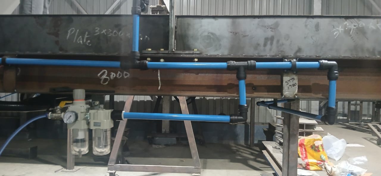
3. Fast, Certified Onsite Erection & Installation
We deploy trained installation teams to execute pipework
erection directly at your factory site. The push-to-connect and
modular clamping system eliminates the need for hot work
permits, threading, welding, or heavy rigging equipment. Our
certified technicians assemble the pipeline ring main, position
drop columns, install quick-drops (which pull dry air from the
top of the line to prevent moisture carry-over), and connect
manifolds near machinery stations. This modularity means
installation takes up to 75% less time than GI
piping, saving on labor costs and allowing your factory to
continue production with zero disruption or downtime.
4. Ultrasonic Leak Detection & Compressed Air Audits
A system is only as good as its seal. Industrial plants waste an
average of 20% to 30% of their compressed air due to silent
leaks in old pipe joints and fittings. C MATIC CONTROL LLP
conducts detailed compressed air energy audits. Using advanced
ultrasonic leak detectors, our engineers
pinpoint even the smallest micro-leaks in your existing network
without interrupting production. We also perform flow metering,
pressure drop tracking, and dew point measurements to assess air
quality. Post-installation, we run a rigorous 1.5× pressure
holding test and supply a certified audit report showing exactly
how much energy your facility is saving.
Industrial Guide to Sizing & Design of Aluminium Compressed
Air Piping
Designing an industrial compressed air distribution network
requires careful hydraulic calculations to minimize operating
costs and prevent equipment malfunctions. Here is how the C
MATIC CONTROL LLP engineering team designs high-performance
Quickair™ aluminium modular piping networks:
1. The Compressed Air Velocity Equation
Air velocity within the piping network is a critical parameter.
High air velocities cause excessive pressure drops, high
turbulence, and carry moisture and contaminants downstream. The
standard velocity equation is: V = (Q * P_atm) / (A *
P_operating) Where: • V = Velocity of air in
meters per second (m/s) • Q = Free Air
Delivery (FAD) flow rate at atmospheric pressure (m³/s or CFM
converted) • P_atm = Atmospheric pressure
(normally 1.013 bar) • A =
Cross-sectional area of the pipe bore (m²) •
P_operating = Absolute operating pressure
inside the pipeline (bar absolute) To maintain laminar
flow and avoid pressure loss, C MATIC CONTROL LLP designs
headers and ring mains to keep velocity under
6 m/s, and drop legs to machine terminals under
15 m/s.
2. Loop (Ring Main) vs. Dead-End Line Layouts
The physical layout of the network determines flow path
flexibility. In a
Closed Loop (Ring Main) system, air travels
from the receiver tank and flows in two directions around the
loop to reach any given usage point. This effectively splits the
flow rate in half for any single pipe segment, reducing the
velocity and pressure drop by up to 75% compared to a single
line. In contrast, a
Dead-End (Header) system forces all air to
travel down a single trunk line. The points furthest from the
compressor suffer from cumulative pressure drops and starved air
volume. C MATIC CONTROL LLP always recommends a closed ring main
design for manufacturing facilities.
3. Mitigating Pressure Drops & Compressor Energy Consumption
Pressure drop is the loss of pressure from the compressor
discharge to the final point of use. Every
1 bar (14.5 psi) of pressure drop in the
distribution network requires the compressor to run
7% to 8% higher, directly increasing
electricity bills. Standard GI pipe networks experience severe
friction over time due to rust scaling, resulting in pressure
drops of 1.0 to 1.5 bar. By utilizing Quickair™ modular tubes
with an ultra-smooth internal bore (roughness ≤ 0.8 μm Ra)
manufactured by Quickair™, C MATIC CONTROL LLP keeps system-wide
pressure drops under 0.1 bar, delivering direct
energy savings.
4. Prevention of Condensate Carry-Over via Goose-Neck Drops
Even with air dryers, compressed air lines can form liquid
moisture (condensate) as the air cools. If drop legs are
connected to the bottom of the header pipe, gravity pulls the
water straight down into pneumatic cylinders and tools, causing
rust, seal breakdown, and product contamination. C MATIC CONTROL
LLP designs all pipeline drops as
Goose-Neck (Quick-Drop) assemblies, which
branch out from the top of the header loop. Moisture remains at
the bottom of the main line to be routed to auto-drains, while
dry air is fed into the drop leg.
Download Quickair Master Catalogue
Access complete technical specifications, diameters, and
installation guidelines (PDF).
Quickair™ Modular Piping System — Product Catalogue
Explore technical dimensions, weights, and pressure parameters of
standard Quickair™ components. Search the catalogue below to find
specific part numbers and specifications:
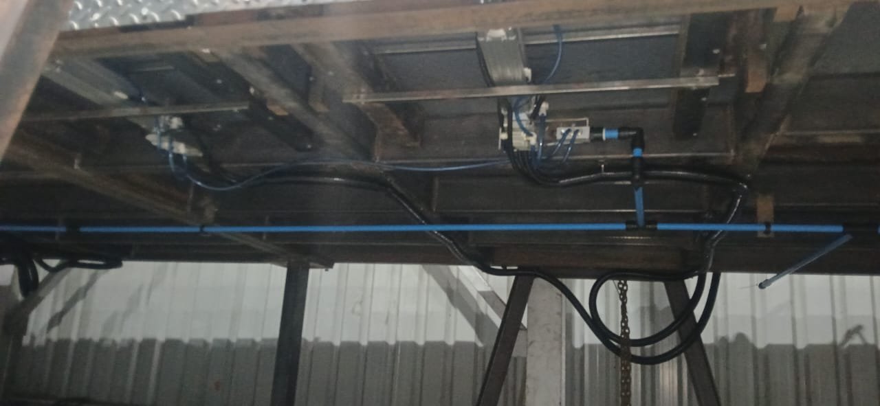
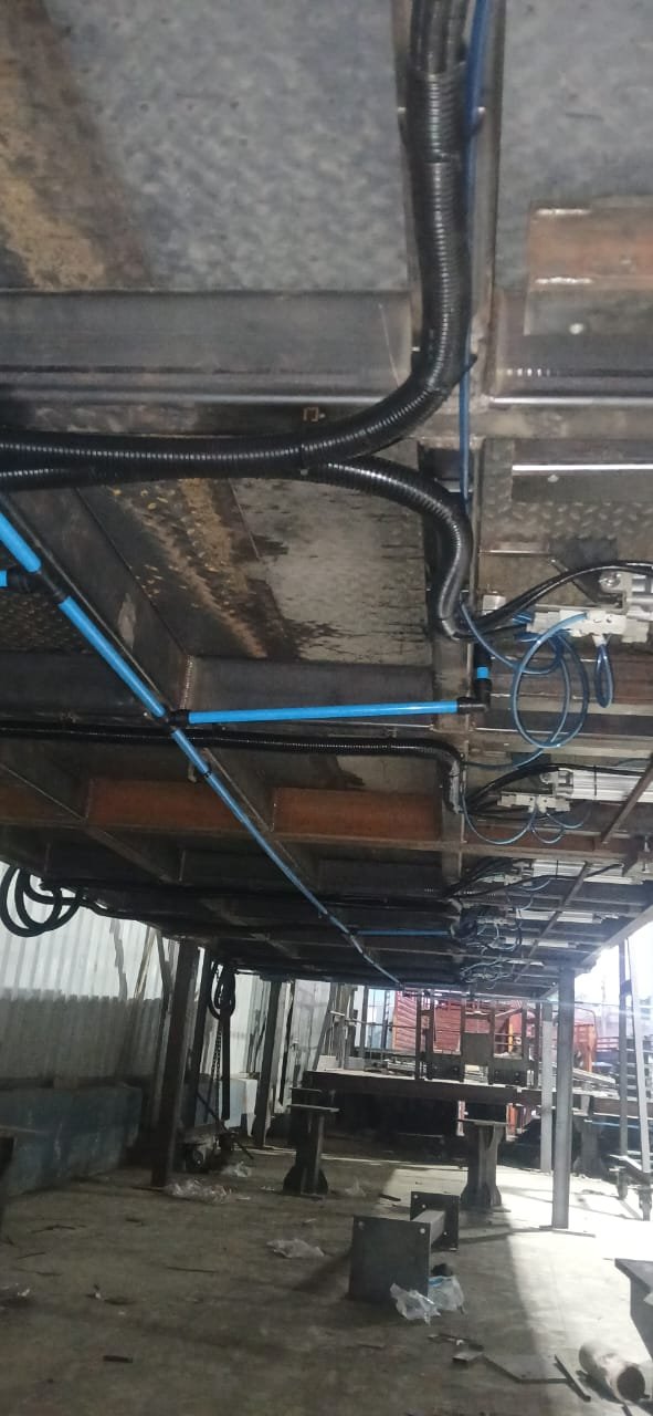
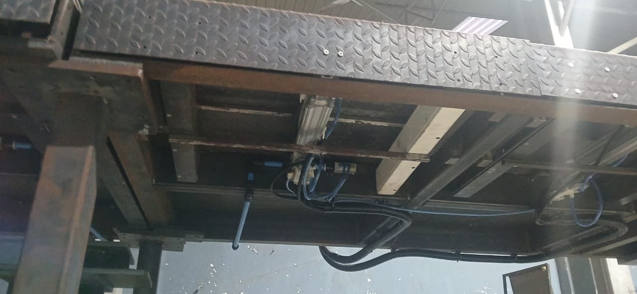
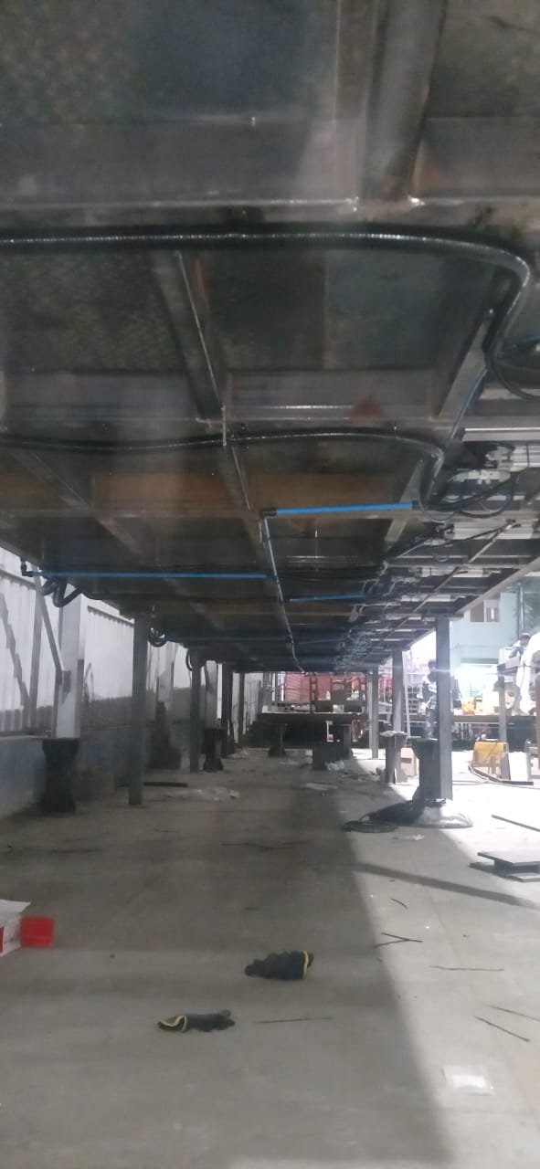
Our Project Installations Gallery — Swipe to Explore
Swipe or drag to browse all project installations
SECTION 1 — COMPONENTS (20mm–63mm) — Aluminium with Engineering
Plastic
1.1 EQUAL TEE
Part No.
Size
D1 (mm)
L1 (mm)
L2 (mm)
PN (bar)
Weight (kg)
ET242000
20mm
36
110
43
20
0.130
ET242500
25mm
42
118
45
20
0.165
ET243200
32mm
55
140
51
20
0.380
ET244000
40mm
69
178
66
20
0.860
ET245000
50mm
80
198
72
20
1.008
ET246300
63mm
95
216
75
20
1.950
1.2 REDUCED TEE
Part No.
Size
D1 (mm)
L1 (mm)
L2 (mm)
PN (bar)
Weight (kg)
RT242520
25mm x 20mm
42
128
45
20
0.215
RT243220
32mm x 20mm
55
150
51
20
0.420
RT243225
32mm x 25mm
55
150
51
20
0.425
RT244020
40mm x 20mm
69
188
66
20
0.905
RT244025
40mm x 25mm
69
188
66
20
0.910
RT244032
40mm x 32mm
69
188
66
20
0.925
RT245020
50mm x 20mm
80
208
72
20
1.005
RT245025
50mm x 25mm
80
208
72
20
1.025
RT245032
50mm x 32mm
80
208
72
20
1.253
RT245040
50mm x 40mm
80
208
72
20
1.325
RT246320
63mm x 20mm
95
226
75
20
1.950
RT246325
63mm x 25mm
95
226
75
20
2.120
RT246332
63mm x 32mm
95
226
75
20
2.213
RT246340
63mm x 40mm
95
226
75
20
2.321
RT246350
63mm x 50mm
95
226
75
20
2.425
1.3 QUICKDROP — Male
Part No.
Size
D1 (mm)
D2 (mm)
L1 (mm)
PN (bar)
Weight (kg)
MD242520
25mm x 20mm
25
20
43
20
0.160
MD243220
32mm x 20mm
32
20
43
20
0.270
MD243225
32mm x 25mm
32
25
45
20
0.250
MD244020
40mm x 20mm
40
20
43
20
0.270
MD244025
40mm x 25mm
40
25
45
20
0.260
MD245020
50mm x 20mm
50
20
43
20
0.300
MD245025
50mm x 25mm
50
25
45
20
0.300
MD246320
63mm x 20mm
63
20
43
20
0.350
MD246325
63mm x 25mm
63
25
45
20
0.350
1.4 PIPE TO PIPE CONNECTOR
Part No.
Size
D1 (mm)
L1 (mm)
L2 (mm)
PN (bar)
Weight (kg)
PP242000
20mm
36
88
43
20
0.086
PP242500
25mm
42
94
45
20
0.093
PP243200
32mm
55
104
51
20
0.021
PP244000
40mm
69
136
66
20
0.420
PP245000
50mm
80
147
72
20
0.525
PP246300
63mm
95
152
75
20
0.680
1.5 ELBOW
Part No.
Size
D1 (mm)
L1 (mm)
L2 (mm)
PN (bar)
Weight (kg)
EL242000
20mm
36
110
43
20
0.090
EL242500
25mm
42
118
45
20
0.113
EL243200
32mm
55
140
51
20
0.250
EL244000
40mm
69
89
66
20
0.490
EL245000
50mm
80
99
72
20
0.634
EL246300
63mm
95
109
75
20
1.230
1.6 REDUCED ELBOW
Part No.
Size
D1 (mm)
L1 (mm)
L2 (mm)
PN (bar)
Weight (kg)
RE242520
25mm x 20mm
42
69
45
20
0.155
RE243220
32mm x 20mm
55
80
51
20
0.315
RE243225
32mm x 25mm
55
80
51
20
0.350
RE244020
40mm x 20mm
69
99
66
20
0.550
RE244025
40mm x 25mm
69
99
66
20
0.555
RE244032
40mm x 32mm
69
99
66
20
0.655
RE245020
50mm x 20mm
80
109
72
20
0.685
RE245025
50mm x 25mm
80
109
72
20
0.710
RE245032
50mm x 32mm
80
109
72
20
0.734
RE245040
50mm x 40mm
80
109
72
20
0.765
RE246320
63mm x 20mm
95
118
75
20
1.333
RE246325
63mm x 25mm
95
118
75
20
1.385
RE246332
63mm x 32mm
95
118
75
20
1.415
RE246340
63mm x 40mm
95
118
75
20
1.435
RE246350
63mm x 50mm
95
118
75
20
1.485
1.7 45° ANGLE ELBOW
Part No.
Size
D1 (mm)
L1 (mm)
L2 (mm)
PN (bar)
Weight (kg)
AE242000
20mm
36
130
43
20
0.180
AE242500
25mm
42
130
45
20
0.250
AE243200
32mm
55
150
54
20
0.450
AE244000
40mm
69
182
66
20
0.700
AE245000
50mm
80
208
72
20
0.870
AE246300
63mm
95
222
75
20
1.600
1.8 MALE CONNECTOR
Part No.
Size
D1 (mm)
L1 (mm)
L2 (mm)
L3 (mm)
BSP
Weight (kg)
MC242005
20mm x 0.5"
36
62
43
14
1/2"
0.070
MC242007
20mm x 0.7"
36
64
43
16
3/4"
0.070
MC242505
25mm x 0.5"
42
62
45
14
1/2"
0.080
MC242507
25mm x 0.7"
42
65
45
16
3/4"
0.090
MC242510
25mm x 1"
42
65
45
16
1"
0.100
MC243210
32mm x 1"
55
69
51
16
1"
0.165
MC243212
32mm x 1.2"
55
70
51
16.5
1 1/4"
0.195
MC244010
40mm x 1"
69
88
66
16
1"
0.365
MC244015
40mm x 1.5"
69
88
66
18
1 1/2"
0.365
MC245015
50mm x 1.5"
80
95
72
18
1 1/2"
0.450
MC245020
50mm x 2"
80
95
72
18
2"
0.460
MC246320
63mm x 2"
95
97
75
18
2"
0.780
MC246325
63mm x 2.5"
95
98
75
19
2 1/2"
0.840
1.9 END CAP
Part No.
Size
D1 (mm)
L1 (mm)
L2 (mm)
PN (bar)
Weight (kg)
EC242000
20mm
36
49
43
20
0.072
EC242500
25mm
42
49
45
20
0.090
EC243200
32mm
55
55
51
20
0.185
EC244000
40mm
69
73
66
20
0.395
EC245000
50mm
80
78
72
20
0.550
EC246300
63mm
95
81
75
20
0.820
1.10 REDUCER
Part No.
Size
D1 (mm)
D2 (mm)
L1 (mm)
L2 (mm)
L3 (mm)
PN (bar)
Weight (kg)
RD242520
25mm x 20mm
42
36
45
43
92
20
1.145
RD243220
32mm x 20mm
55
36
51
43
98
20
0.230
RD243225
32mm x 25mm
55
42
51
45
98
20
0.235
RD244020
40mm x 20mm
69
36
66
43
114
20
0.370
RD244025
40mm x 25mm
69
42
66
45
114
20
0.380
RD244032
40mm x 32mm
69
55
66
51
120
20
0.520
RD245020
50mm x 20mm
80
36
72
43
120
20
0.420
RD245025
50mm x 25mm
80
42
72
45
120
20
0.480
RD245032
50mm x 32mm
80
55
72
51
126
20
0.550
RD245040
50mm x 40mm
80
69
72
66
142
20
0.850
RD246320
63mm x 20mm
95
36
75
43
122
20
0.740
RD246325
63mm x 25mm
95
42
75
45
122
20
0.760
RD246332
63mm x 32mm
95
55
75
51
128
20
0.840
RD246340
63mm x 40mm
95
69
75
66
144
20
1.040
RD246350
63mm x 50mm
95
80
75
72
150
20
1.300
1.11 FEMALE THREADED TEE
Part No.
Size
D1 (mm)
L1 (mm)
L2 (mm)
BSP
PN (bar)
Weight (kg)
FT242005
20mm x 0.5"
36
110
43
0.5"
20
0.150
FT242007
20mm x 0.7"
36
110
43
0.7"
20
0.175
FT242505
25mm x 0.5"
42
118
45
0.5"
20
0.216
FT242507
25mm x 0.7"
42
118
45
0.7"
20
0.195
FT242510
25mm x 1"
42
118
45
1"
20
0.180
FT243205
32mm x 0.5"
55
140
51
0.5"
20
0.415
FT243207
32mm x 0.7"
55
140
51
0.7"
20
0.395
FT243210
32mm x 1"
55
140
51
1"
20
0.385
FT244005
40mm x 0.5"
69
178
66
0.5"
20
0.860
FT244007
40mm x 0.7"
69
178
66
0.7"
20
0.850
FT244010
40mm x 1"
69
178
66
1"
20
0.830
FT245005
50mm x 0.5"
80
198
72
0.5"
20
1.125
FT245007
50mm x 0.7"
80
198
72
0.7"
20
1.001
FT245010
50mm x 1"
80
198
72
1"
20
0.950
FT246305
63mm x 0.5"
95
216
75
0.5"
20
1.985
FT246307
63mm x 0.7"
95
216
75
0.7"
20
1.852
FT246310
63mm x 1"
95
216
75
1"
20
1.750
1.12 DROPLETS — Female Thread (Aluminium with Aluminium)
Part No.
Size
D1 (mm)
BSP
L1 (mm)
PN (bar)
Weight (kg)
FD242505
25mm x 0.5"
25
1/2"
14
20
0.160
FD242507
25mm x 0.7"
25
3/4"
16
20
0.140
FD243205
32mm x 0.5"
32
1/2"
14
20
0.280
FD243207
32mm x 0.7"
32
3/4"
16
20
0.260
FD243210
32mm x 1"
32
1"
19
20
0.250
FD244005
40mm x 0.5"
40
1/2"
14
20
0.320
FD244007
40mm x 0.7"
40
3/4"
16
20
0.310
FD244010
40mm x 1"
40
1"
19
20
0.301
FD245005
50mm x 0.5"
50
1/2"
14
20
0.340
FD245007
50mm x 0.7"
50
3/4"
16
20
0.320
FD245010
50mm x 1"
50
1"
19
20
0.310
FD246305
63mm x 0.5"
63
1/2"
14
20
0.380
FD246307
63mm x 0.7"
63
3/4"
16
20
0.360
FD246310
63mm x 1"
63
1"
19
20
0.340
1.13 PIPE COUPLER (Aluminium with Aluminium)
Part No.
Size
L1 (mm)
L2 (mm)
L3 (mm)
PN (bar)
Weight (kg)
PC243000
3"
162
80
109
20
0.520
PC244100
4"
186
90
132
20
0.950
PC244600
6"
192
100
190
20
1.300
PC248000
8"
300
120
250
20
1.800
SECTION 2 — COMPONENTS (76mm–219mm) — Aluminium with Aluminium
2.1 ENDCAP
Part No.
Size
D1 (mm)
D2 (mm)
L1 (mm)
PN (bar)
Weight (kg)
EC243000
3"
90.0
95
50
20
0.259
EC244100
4"
113.5
120
70
20
0.312
EC246000
6"
168.3
176
80
20
0.340
EC248000
8"
219.1
228
90
20
0.450
2.2 EQUAL TEE
Part No.
Size
D1 (mm)
L1 (mm)
L2 (mm)
PN (bar)
Weight (kg)
ET243000
3"
90.0
280
140
20
1.390
ET244100
4"
113.5
330
165
20
2.160
ET246000
6"
168.3
400
200
20
6.000
ET248000
8"
219.1
500
250
20
10.000
2.3 DROP
Part No.
Size
D1 (mm)
A (mm)
B (mm)
C
PN (bar)
Weight (kg)
FD243005
3" x 0.5"
90
133
155
1/2" BSP
20
0.500
FD243007
3" x 0.7"
90
133
155
3/4" BSP
20
0.470
MD243020
3" x 2"
90
133
155
20MM
20
0.470
MD243025
3" x 2.5"
90
133
155
25MM
20
0.450
FD244105
4" x 0.5"
113.5
160
182
1/2" BSP
20
0.610
FD244107
4" x 0.7"
113.5
160
182
3/4" BSP
20
0.580
MD244120
4" x 2"
113.5
160
182
20MM
20
0.600
MD244125
4" x 2.5"
113.5
160
182
25MM
20
0.570
FD246005
6" x 0.5"
168.3
200
240
1/2" BSP
20
1.110
FD246007
6" x 0.7"
168.3
200
240
3/4" BSP
20
1.050
MD246020
6" x 2"
168.3
200
240
20MM
20
1.100
MD246025
6" x 2.5"
168.3
200
240
25MM
20
1.070
FD248005
8" x 0.5"
219.1
270
300
1/2" BSP
20
1.610
FD248007
8" x 0.7"
219.1
270
300
3/4" BSP
20
1.510
MD248020
8" x 2"
219.1
270
300
20MM
20
1.500
MD248025
8" x 2.5"
219.1
270
300
25MM
20
1.600
2.4 ELBOW
Part No.
Size
D1 (mm)
L1 (mm)
PN (bar)
Weight (kg)
EL243000
3"
90.0
140
20
0.940
EL244100
4"
113.5
165
20
1.530
EL246000
6"
168.3
200
20
5.000
EL248000
8"
219.1
250
20
9.000
2.5 REDUCER
Part No.
Size
D1 (mm)
Ø2 (mm)
L1 (mm)
L2 (mm)
L3 (mm)
PN (bar)
Weight (kg)
RD243040
3" x 40mm
90
40
175
95
70
20
0.529
RD243050
3" x 50mm
90
50
190
95
85
20
0.576
RD243063
3" x 63mm
90
63
201
95
96
20
0.630
RD244140
4" x 40mm
113.5
40
195
115
70
20
0.797
RD244150
4" x 50mm
113.5
50
210
115
85
20
0.844
RD244163
4" x 63mm
113.5
63
215
115
90
20
0.884
RD244130
4" x 3"
113.5
90
220
115
95
20
0.947
RD246040
6" x 40mm
168.3
40
225
145
70
20
1.490
RD246050
6" x 50mm
168.3
50
240
145
85
20
1.536
RD246063
6" x 63mm
168.3
63
245
145
90
20
1.576
RD246030
6" x 3"
168.3
90
250
145
95
20
1.639
RD246041
6" x 4"
168.3
113.5
270
145
115
20
1.762
RD248040
8" x 40mm
219.1
40
235
155
70
20
2.181
RD248050
8" x 50mm
219.1
50
250
155
85
20
2.227
RD248063
8" x 63mm
219.1
63
255
155
90
20
2.267
RD248030
8" x 3"
219.1
90
260
155
95
20
2.330
RD248041
8" x 4"
219.1
113.5
280
155
115
20
2.453
RD248060
8" x 6"
219.1
168.3
310
155
145
20
2.707
2.6 FLANGED END
Part No.
Size
D1 (mm)
L1 (mm)
T (mm)
PCD (mm)
Ø (mm)
PN (bar)
Weight (kg)
FE243000
3"
90.0
95
23.8
152.4
190.5
20
1.820
FE244100
4"
113.5
115
23.8
190.5
228.6
20
2.430
FE246000
6"
168.3
145
25.4
241.3
279.4
20
2.900
FE248000
8"
219.1
155
28.4
298.4
342.9
20
4.000
2.7 REDUCING TEE
Part No.
Size
L1 (mm)
L2 (mm)
D1 (mm)
D2 (mm)
PN (bar)
Weight (kg)
RT243040
3" x 40mm
280
110
90
40
20
0.700
RT243050
3" x 50mm
280
135
90
50
20
0.740
RT243063
3" x 63mm
280
135
90
63
20
0.770
RT244140
4" x 40mm
330
135
113.5
40
20
1.050
RT244150
4" x 50mm
330
135
113.5
50
20
1.060
RT244163
4" x 63mm
330
155
113.5
63
20
1.120
RT244130
4" x 3"
330
165
113.5
90
20
1.900
RT246040
6" x 40mm
400
155
168.3
40
20
2.200
RT246050
6" x 50mm
400
175
168.3
50
20
2.320
RT246063
6" x 63mm
400
175
168.3
63
20
2.350
RT246030
6" x 3"
400
185
168.3
90
20
2.300
RT246041
6" x 4"
400
200
168.3
113.5
20
2.900
RT248040
8" x 40mm
500
175
219.1
40
20
3.720
RT248050
8" x 50mm
500
175
219.1
50
20
3.730
RT248063
8" x 63mm
500
200
219.1
63
20
3.800
RT248030
8" x 3"
500
210
219.1
90
20
3.840
RT248041
8" x 4"
500
225
219.1
113.5
20
3.920
RT248060
8" x 6"
500
225
219.1
168.3
20
4.100
SECTION 3 — MANIFOLDS
3.1 MANIFOLD With Mini Ball Valve (Horizontal)
Part No.
Size
Outlets
PN (bar)
L1 (mm)
L2 (mm)
Weight (kg)
GM321204
1¼" (32)
4
20
600
125
10
GM321206
1¼" (32)
6
20
600
125
10
GM401504
1½" (40)
4
20
600
130
12
GM401506
1½" (40)
6
20
600
130
12
GM502004
2" (50)
4
20
600
135
15
GM502006
2" (50)
6
20
600
135
15
GM632504
2½" (63)
4
20
600
140
18
GM632506
2½" (63)
6
20
600
140
18
GM753004
3" (75)
4
20
600
145
21
GM753006
3" (75)
6
20
600
145
21
GM10004
4" (100)
4
20
600
150
25
GM10006
4" (100)
6
20
600
150
25
3.2 MANIFOLD With Mini Ball Valve (Vertical)
Part No.
Size
Outlets
PN (bar)
L1 (mm)
L2 (mm)
Weight (kg)
GM321204
1¼" (32)
4
20
600
125
10
GM321206
1¼" (32)
6
20
600
125
10
GM401504
1½" (40)
4
20
600
130
12
GM401506
1½" (40)
6
20
600
130
12
GM502004
2" (50)
4
20
600
135
15
GM502006
2" (50)
6
20
600
135
15
GM632504
2½" (63)
4
20
600
140
18
GM632506
2½" (63)
6
20
600
140
18
GM753004
3" (75)
4
20
600
145
21
GM753006
3" (75)
6
20
600
145
21
GM10004
4" (100)
4
20
600
150
25
GM10006
4" (100)
6
20
600
150
25
3.3 MANIFOLD With Inbuilt Valve (Horizontal)
Part No.
Size
Outlets
PN (bar)
L1 (mm)
L2 (mm)
Weight (kg)
GMIBV321204
1¼" (32)
4
20
600
125
10
GMIBV321206
1¼" (32)
6
20
600
125
10
GMIBV401504
1½" (40)
4
20
600
130
12
GMIBV401506
1½" (40)
6
20
600
130
12
GMIBV502004
2" (50)
4
20
600
135
15
GMIBV502006
2" (50)
6
20
600
135
15
GMIBV632504
2½" (63)
4
20
600
140
18
GMIBV632506
2½" (63)
6
20
600
140
18
GMIBV753004
3" (75)
4
20
600
145
21
GMIBV753006
3" (75)
6
20
600
145
21
GMIBV10004
4" (100)
4
20
600
150
25
GMIBV10006
4" (100)
6
20
600
150
25
3.4 MANIFOLD With Inbuilt Valve (Vertical)
Part No.
Size
Outlets
PN (bar)
L1 (mm)
L2 (mm)
Weight (kg)
GMIBV321204
1¼" (32)
4
20
600
125
10
GMIBV321206
1¼" (32)
6
20
600
125
10
GMIBV401504
1½" (40)
4
20
600
130
12
GMIBV401506
1½" (40)
6
20
600
130
12
GMIBV502004
2" (50)
4
20
600
135
15
GMIBV502006
2" (50)
6
20
600
135
15
GMIBV632504
2½" (63)
4
20
600
140
18
GMIBV632506
2½" (63)
6
20
600
140
18
GMIBV753004
3" (75)
4
20
600
145
21
GMIBV753006
3" (75)
6
20
600
145
21
GMIBV10004
4" (100)
4
20
600
150
25
GMIBV10006
4" (100)
6
20
600
150
25
3.5 MANIFOLD With Quick Coupler
Part No.
Size
Outlets
PN (bar)
L1 (mm)
L2 (mm)
Weight (kg)
CAMPI2504
1" (25)
4
20
260
110
3
3.6 MANIFOLD With Mini Ball Valves
Part No.
Size
Outlets
PN (bar)
L1 (mm)
L2 (mm)
Weight (kg)
CAMPIBN2504
1" (25)
4
20
260
110
3
SECTION 4 — WALL BRACKETS
4.1 INLINE BALL VALVE With Male Connector
Part No.
Size
L1 (mm)
PN (bar)
Weight (kg)
INBVMC2005
20mm x 1/2"
170
20
0.29
INBVMC2007
20mm x 3/4"
180
20
0.35
INBVMC2505
25mm x 1/2"
170
20
0.31
INBVMC2507
25mm x 3/4"
182
20
0.39
INBVMC2510
25mm x 1"
190
20
0.52
INBVMC3210
32mm x 1"
198
20
0.65
INBVMC3212
32mm x 1 1/4"
202
20
0.87
INBVMC4010
40mm x 1"
236
20
1.05
INBVMC4015
40mm x 1 1/2"
259
20
1.41
INBVMC5015
50mm x 1 1/2"
278
20
1.58
INBVMC5020
50mm x 2"
279
20
2.72
INBVMC6320
63mm x 2"
283
20
3.36
INBVMC6325
63mm x 2 1/2"
306
20
3.89
INBVMC3025
90mm x 2 1/2"
357
20
4.30
INBVMC3030
90mm x 3"
362
20
4.50
4.2 WALL BRACKET ½" OUTLET 2WAY
Part No.
Size
D1 (mm)
D2 (mm)
L1 (mm)
L2 (mm)
L3 (mm)
L4 (mm)
PN (bar)
Weight (kg)
WB242005
20mm x 0.5"
68
36
140
40
79
43
20
0.550
WB242505
25mm x 0.5"
68
42
140
40
79
45
20
0.570
4.3 WALL BRACKET ½" OUTLET 2WAY With DRAIN NUT
Part No.
Size
D1 (mm)
D2 (mm)
L1 (mm)
L2 (mm)
L3 (mm)
L4 (mm)
PN (bar)
Weight (kg)
WB242005D
20mm x 0.5"
68
36
140
40
79
43
20
0.550
WB242505D
25mm x 0.5"
68
42
140
40
79
45
20
0.570
4.4 WALL BRACKET ½" OUTLET 2WAY With VALVE (Inbuilt)
Part No.
Size
D1 (mm)
D2 (mm)
L1 (mm)
L2 (mm)
L3 (mm)
L4 (mm)
PN (bar)
Weight (kg)
TWBO242005
20mm x 0.5"
68
36
140
40
79
43
20
0.550
TWBO242505
25mm x 0.5"
68
42
140
40
79
45
20
0.570
4.5 SINGLE WAY WALL BRACKET
Part No.
Size
D1 (mm)
L1 (mm)
L2 (mm)
L3 (mm)
PN (bar)
Weight (kg)
WB24012005
20mm x 0.5"
20
120
42
65
20
0.525
WB24012505
25mm x 0.5"
25
120
42
65
20
0.550
SECTION 5 — VALVES
5.1 3 Piece INLINE BALL VALVE
Part No.
Size (mm)
PN (bar)
L1 (mm)
Weight (kg)
BF242045
20
20
135
1.00
BF242554
25
20
168
2.10
BF243262
32
20
199
2.80
BF244074
40
20
202
3.20
BF245088
50
20
204
4.50
BF246307
63
20
224
7.37
5.2 3 Piece INLINE MALE BALL VALVE
Part No.
Size (mm)
PN (bar)
L1 (mm)
Weight (kg)
BF24M2007
20
20
135
0.80
BF24M2510
25
20
168
1.60
BF24M3212
32
20
199
2.10
BF24M4015
40
20
202
3.00
BF24M5020
50
20
204
4.00
BF24M6325
63
20
224
7.37
5.3 3 Piece INLINE FEMALE BALL VALVE
Part No.
Size (mm)
PN (bar)
L1 (mm)
Weight (kg)
BF24F2007
20
20
135
0.80
BF24F2510
25
20
168
1.60
BF24F3212
32
20
199
2.10
BF24F4015
40
20
202
3.00
BF24F5020
50
20
204
4.00
BF24F6325
63
20
224
7.37
5.4 FEMALE THREADED INLINE BALL VALVE (Brass)
Part No.
Size (mm)
PN (bar)
L1 (mm)
L2 (mm)
Weight (kg)
INBVF2007
20
20
75
70
0.35
INBVF2510
25
20
85
75
0.50
5.5 INLINE BALL VALVE (Brass)
Part No.
Size (mm)
PN (bar)
L1 (mm)
L2 (mm)
Weight (kg)
INBV20
20
20
90
70
0.35
INBV25
25
20
100
75
0.50
5.6 MINI BALL VALVE (Brass)
Part No.
Size
PN (bar)
L1 (mm)
L2 (mm)
Weight (kg)
MBVMF0500
1/2"
20
48
44
0.20
5.7 BUTTERFLY VALVE (CI)
Part No.
Size
A (mm)
B (mm)
C (mm)
D (mm)
E (mm)
F (mm)
G (mm)
H (mm)
I (mm)
PN (bar)
Weight (kg)
80-83-22-23-EM-150#
3"
46
15
81
50
17
7
65
255
195
16
3.500
100-83-22-23-EM-150#
4"
52
15
103
50
17
7
65
284
195
16
4.750
150-83-22-23-EM-150#
6"
56
19
153
70
17
9
90
358
320
16
9.150
200-83-22-23-EM-150#
8"
60
19
201
70
97
9
90
421
320
16
16.000
5.8 BALL VALVE
Part No.
Size
A (mm)
B (mm)
C (mm)
PN (bar)
Weight (kg)
BV110200
1/4"
90
38
48
16
0.100
BV110500
1/2"
90
46
58
16
0.150
BV110700
3/4"
90
52
65
16
0.213
BV111000
1"
106
60
69
16
0.318
BV111200
1 1/2"
110
62
80
16
0.480
BV111500
1 1/2"
148
83
92
16
0.680
BV112000
2"
148
89
110
16
1.800
BV112500
2 1/2"
217
110
132
16
2.206
SECTION 6 — TOOLS & CLIPS
6.1 CRIMPING JAWS (CJ13)
Part No.
Size
Weight (kg)
CJ133000
3"
5
CJ134100
4"
5
CJ136000
6"
5
CJ138000
8"
5
6.2 CAP OPENING TOOL
Part No.
Size
Weight (kg)
OT132000
20
0.158
OT132500
25
0.152
OT133200
32
0.252
OT134000
40
0.318
OT135000
50
0.330
OT136300
63
0.409
6.3 TUBE CUTTER
Part No.
Size
Weight (kg)
TC110100
20–63mm
0.380
6.4 DEBURING TOOL
Part No.
Size
Weight (kg)
DB110000
20mm to 8"
0.028
6.5 CRIMPING MACHINE
Part No.
Size
Weight (kg)
CM130000
3" to 8"
3
6.6 U-BOLT
Part No.
Size
Ø1 (mm)
Weight (kg)
UBLT16M83000
3"
90.00
0.100
UBLT16M84100
4"
113.5
0.120
UBLT16M86000
6"
168.3
0.155
UBLT16M88000
8"
219.1
0.189
6.7 CHAMFERING TOOL
Part No.
Size
Weight (kg)
CT110100
20–50mm
0.530
6.8 CHAMFERING TOOL FOR LARGER DIA
Part No.
Size
Weight (kg)
CT110101
63–90mm / 4" & 5"
2.000
6.9 CLIP
Part No.
Size
Weight (kg)
PH132000
20
0.120
PH132500
25
0.130
PH133200
32
0.140
PH134000
40
0.158
PH135000
50
0.188
PH136300
63
0.200
6.10 OPENING CLIP
Part No.
Size
Weight (kg)
OC132000
20
0.006
OC132500
25
0.008
OC133200
32
0.010
OC134000
40
0.015
OC135000
50
0.019
OC136300
63
0.022
6.11 CLIPS
Part No.
Size
Weight (kg)
CL112000
20
0.015
CL112500
25
0.018
CL113200
32
0.023
CL114000
40
0.066
CL115000
50
0.084
CL116300
63
0.113
SECTION 7 — ACCESSORIES
7.1 MALE SOCKET
Part No.
Size
Weight (kg)
SM110200
1/4"
0.150
SM110300
3/8"
0.250
SM110500
1/2"
0.350
SM110700
3/4"
0.450
SM110000
1"
0.550
7.2 MALE PLUG
Part No.
Size
Weight (kg)
PM110200
1/4"
0.050
PM110300
3/8"
0.050
PM110500
1/2"
0.050
PM110700
3/4"
0.070
PM111000
1"
0.090
7.3 FEMALE SOCKET
Part No.
Size
Weight (kg)
SF110200
1/4"
0.200
SF110300
3/8"
0.250
SF110500
1/2"
0.350
SF110700
3/4"
0.450
SF111000
1"
0.500
7.4 FEMALE PLUG
Part No.
Size
Weight (kg)
PF110200
1/4"
0.200
PF110300
3/8"
0.250
PF110500
1/2"
0.300
PF110700
3/4"
0.350
PF111000
1"
0.400
7.5 HOSE SOCKET
Part No.
Size
Weight (kg)
SH110340
3/8"
0.200
SH110540
1/2"
0.300
SH110740
3/4"
0.400
SH111040
1"
0.500
7.6 NUT SOCKET
Part No.
Size
Weight (kg)
SN110800
08
0.300
SN111000
10
0.400
SN111200
12
0.500
7.7 NUT PLUG
Part No.
Size
Weight (kg)
PN110800
08
0.080
PN111000
10
0.100
PN111200
12
0.120
PN111400
14
0.150
7.8 HOUSE PLUG
Part No.
Size
Weight (kg)
PH110200
1/4"
0.100
PH110300
3/8"
0.120
PH110500
1/2"
0.220
PH110700
3/4"
0.350
PH111000
1"
0.400
7.9 FR — Filter Regulator (FR11)
Part No.
Size
FR110200
1/4"
FR110500
1/2"
FR110700
3/4"
FR111000
1"
7.10 FRL — Filter Regulator Lubricator (FL11)
Part No.
Size
FL110200
1/4"
FL110500
1/2"
FL110700
3/4"
FL111000
1"
7.11 POLYURETHANE TUBE (PT11)
MOC: Polyurethane — available in 1000 mtr rolls. Suffix standard
color code: 00=Transparent, 01=Blue (Std), 02=Yellow, 03=Green,
04=Black, 05=Red.
Part No.
ØD
PT110401*
04
PT110601*
06
PT110801*
08
PT111001*
10
PT111201*
12
7.12 RECOIL HOSE (RH11)
MOC: Polyurethane. Available in 2, 3, 5, 6, 8 & 10 mtr lengths
(add length to part number when ordering, e.g. RH110605 = 5 mtr
length of 6mm OD).
Part No.
ØD
RH110403*
04
RH110603*
06
RH110803*
08
RH111003*
10
RH111203*
12
7.13 EXPANSION HOSE (EH11)
Available in 1, 2 & 3 mtr lengths (add length to part number,
e.g. EH112505.1 = 1 mtr).
Part No.
ØD
Size
Part No.
ØD
Size
EH112505*
25
1/2"
EH114012*
40
1¼"
EH112507*
25
3/4"
EH114015*
40
1½"
EH112510*
25
1"
EH115015*
50
1½"
EH113210*
32
1"
EH115020*
50
2"
EH113212*
32
1¼"
EH116320*
63
2"
EH114010*
40
1"
EH116325*
63
2½"
7.14 HEX NIPPLE (HN16)
Part No.
ØC
K (mm)
H (mm)
Weight (kg)
HN160500
1/2"
15
36
0.083
HN160700
3/4"
16
38
0.129
HN161000
1"
16
48
0.250
HN161200
1 1/4"
23
58
0.366
HN161500
1 1/2"
24
63
0.776
HN162000
2"
28
81
1.000
7.15 L ANGLE (LA11)
Part No.
H
L
Weight (kg)
LA110304
3"
4"
0.300
LA110408
4"
8"
0.500
LA110604
6"
4"
0.400
LA110606
6"
6"
0.550
LA110608
6"
8"
0.600
LA110609
6"
9"
0.700
LA110612
6"
12"
0.900
LA111024
10"
24"
1.200
7.16 AIR GUN
Part No.
Weight (kg)
AG110200
0.153
7.17 BUSH WITH O RING GASKET (BS13)
Part No.
Ø
Weight (kg)
BSO132000
20
0.001
BSO132500
25
0.002
BSO133200
32
0.008
BSO134000
40
0.019
BSO135000
50
0.026
BSO136300
63
0.038
7.18 CAP WITH RETAINER RINGS (BO13)
Part No.
Ø
Weight (kg)
CS132000
20
0.002
CS132500
25
0.004
CS133200
32
0.018
CS134000
40
0.044
CS135000
50
0.056
CS136300
63
0.066
7.19 U CLAMP (UC11)
Part No.
H (mm)
L (mm)
W (mm)
Weight (kg)
UC110000
57
26
21
0.102
Frequently Asked Questions (FAQs)
Why choose aluminium over GI (Galvanized Iron) pipes for
compressed air?
Aluminium pipes do not rust or corrode over time, preventing
downstream scaling that damages pneumatic machinery.
Furthermore, their smooth inner walls reduce friction and
pressure drops, lowering compressor power consumption, and
they are much lighter and faster to install.
What is the pressure rating of Quickair™ piping systems?
Standard Quickair™ aluminium piping systems are rated for
working pressures of up to 20 bar (290 psi) within standard
temperature limits, which easily covers typical industrial
automation ranges (6 to 10 bar) and heavy-duty demands.
Special 40 bar systems are available for PET blow molding.
Does C MATIC CONTROL LLP provide post-installation testing
and air audits?
Yes, C MATIC CONTROL LLP provides detailed air audits,
including leak detection using ultrasonic equipment,
pressure drop testing, and flow measurement, ensuring
maximum efficiency and energy savings.
Does the Quickair™ system require welding or threading?
No, Quickair™ features push-to-fit modular fittings that
eliminate the need for welding, soldering, or threading.
This speeds up installation, eliminates hot work permits,
and makes future system modifications incredibly simple.
Can Quickair™ pipelines handle oil-free air?
Yes, the smooth, powder-coated internal surface of the
extruded aluminium tube has zero chemical reaction with
oil-free air. HNBR sealing rings are compatible with both
synthetic lubricants and dry, oil-free industrial air.
How long does installation typically take?
Because of the lightweight components and quick push-fit
joint assemblies, a 100-meter ring main installation
typically takes just 3 to 5 days, which is up to 75% faster
than traditional GI piping.
Does C MATIC CONTROL LLP offer a warranty on the piping
system?
Yes, we offer a comprehensive warranty against
manufacturing defects on all Quickair™ piping components
installed by our engineering team, along with an
installation warranty.
Does C MATIC CONTROL LLP execute projects outside Mumbai?
Yes, C MATIC CONTROL LLP has a national project execution
capability. Our installation crews travel to manufacturing
facilities across Maharashtra, Gujarat, Karnataka, Tamil
Nadu, NCR, and other industrial belts.